
Questa è una vecchia versione del documento!
Indice
Sanco 8003
Sanco 8003 is a Z80 based personal computer, from year 1982.
We got one in working conditions, but we have no operating system disk, no keyboard, and we known nothing about this computer: it just turns on and shows V1.01 on its CRT display.

This is the home page of our project of history documentation on this computer.
We gave it the codename CEDA, as our device came with a shiny proud sticker saying “CEDA”, which probably just stands for Centro Elaborazione Dati (Datacenter, in Italian).
This page contains some (hopefully) useful information about this computer, that we inferred by reverse engineering it with a tester, an oscilloscope, some datasheets and some luck.
Please note that this is a 40 years old not state-of-the-art anymore computer: we only want to document it to help other people fix their - and to hope they help us the other way around.
We don't want to compete with Sanyo, or disclose its intellectual property 
 Warning: we make our best effort to document what we find, but everything that you read here must be taken with extreme care! You may harm your computer or harm yourself if you are not aware of what you are doing, or if there are some errors in this document.
Components
Central unit is composed by several components. Have a look at the table of contents of this page to quickly navigate to the details.
- power supply
- sound speaker
- floppy disk drive (x2)
- green CRT display
- CRT driver board
- computer motherboard
- peripheral connectors daughterboard
External connectors:
- standard C13/C14 power connector
- 5pin DIN for keyboard
- DB25 communication port (supposedly a serial port)
- DB25 printer port (supposedly a standard parallel port)
- 8pin DIN PRNT port
Power supply
- Original PSU
- black → GND
- red → 12V
- yellow → 5V
- purple → -12V
On the power connector on the motherboard there is a key between position 7 and 8, to avoid inserting the plug backwards.
- 1 → GND
- 2 → GND
- 3 → 5V
- 4 → 5V
- 5 → -12V
- 6 → +12 V
- 7 → NC
- EMPTY
- 8 → NC
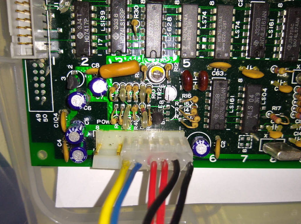 A modern ATX PSU can be used to power the Sanco, just swap yellow and red wires, as shown in the picture. |
Motherboard
 Motherboard is organized as a grid, whose rows are identified by letters, and columns by numbers.
In each cell of the grid, an IC can be located (sometimes one IC spawns more cells, sometimes cells only have passive or analog components).
Motherboard is organized as a grid, whose rows are identified by letters, and columns by numbers.
In each cell of the grid, an IC can be located (sometimes one IC spawns more cells, sometimes cells only have passive or analog components).
Note that row identification letters don't follow strict alphabetical order.
| motherboard | Logic Systems Int'l inc. FPX-290 |
| daughterboard | Logic Systems Int'l inc. FPX-290-CN-01 |
Some documentation recovered from direct inspection:
- Motherboard and daughterboard ICs and their locations: PDF
Connectors
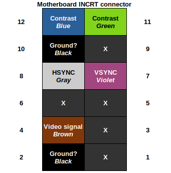
- Display port connector (INCRT) pinout: PDF
- 1 → NC
- 2 → GND (black)
- 3 → NC
- 4 → BEAM Pixels (brown)
- 5 → NC
- 6 → NC
- 7 → Vertical Sync (violet)
- 8 → Horizontal Sync (gray)
- 9 → NC
- 10 → GND (black)
- 11 → CONTRAST (green)
- 12 → CONTRAST (blue)
Schematics
- Schematics (work in progress)
Default settings
As we found on our working computer.
| Location | Type | Name | Description | Default value |
|---|---|---|---|---|
| A12 | DIP switch | 0x8F (bit 12345678) | ||
| B15 | jumper | KB SEL | shorted on PCB | |
| C13 | jumper (3×2) | SIO clock | serial clock |  |
ROM
Memory map
Memory space
| base | size | description |
| 0x0000 | 0x2000 | Software ROM |
| 0x2000 | ||
| 0xC000 | 0x2000 | Software ROM |
| 0xD000 | 0x800 | Video Frame Buffer |
| 0xD800 |
I/O
| address | size | device |
| 0x81 | Bank switching? | |
| 0x83 | ||
| 0xA0 | 2 | CRTC internal registers |
| 0xB0 | 4 | SIO/2 Serial Peripheral |
| 0xC0 | ||
| 0xD5 | 0 | Speaker |
| 0xD6 | ||
| 0xE0 | 4 | CTC Timer |
Software ROM
Character ROM
Each character is 8×16 pixels. There are even placeholders for ASCII control codes. 


Glue ROM
- bit 0-3 → bit 0-3 char ROM
- bit 4-6 →

- bit 7 → char ROM Chip Enable (CE)
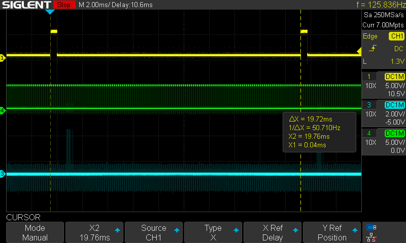
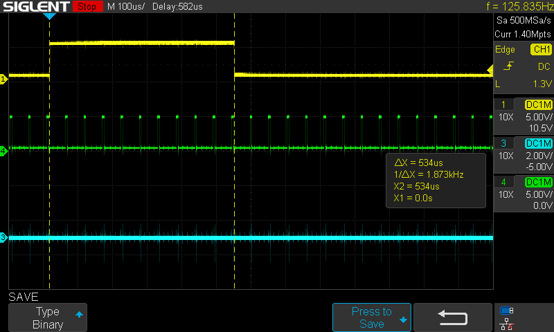
CRT Display
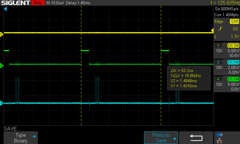
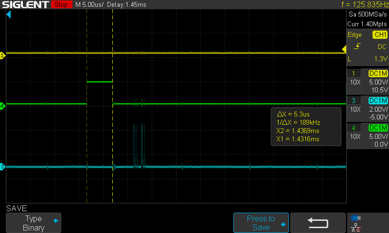
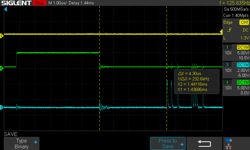
CRT display is controlled by the CRTC circuit. All signals are “digital” TTL levels (0-5V), which are then interpreted by the CRT HV driver board.
| Vertical Sync | ~20 ms |
| Horizontal Sync | 53 us |
| Lines | 370 lines |
| Pixel Clock | 15MHz (XTAL3) |
These signals are not compatible with a common PAL TV-set monitor, neither the voltages nor the timings. If you want to use an external monitor, some active and complex circuit is needed.
See oscilloscope pictures:
TODO
document CRT signals with oscilloscope- document floppy signals (see floppy controller IC)
- disassembly software ROM
dump J12 ROM (TBP28L22M) with ad-hoc hardware- document Z80 addressing space and make some hypothesis about I/O addressing space
- schematics WORK IN PROGRESS
Contacts
We don't know much about this computer. The Internet doesn't either. For any question or any useful information, contact us.